|
RV Electrical Tutorial
Chapter 1 - Introduction to Electricity
Electricity isn't that difficult to understand. Part of the mystique is that it is invisible so
people tend to get confused but if you think of it in terms of water flow you'll probably understand it much easier.
With a plumbed water system you have water pipes, water pressure (PSI), and flow rates (GPM). Electricity is basically
the same thing except you now have electrical wires, voltage, and amperage replacing those three items. Instead of
running a sprinkler or water driven motor you are powering a light bulb or electric motor.
Water pressure represents the force behind the water - the ability to move it along. This is
measured in pounds per square inch (PSI). Electricity also has force - the ability to move those electrons down the line.
This is measured in volts. The actual amount, or volume, of water that flows through the line is measured in Gallons Per
Minute (GPM). In electricity the actual amount of electrons flowing through the line, or current flow, is measured in amps.
Water needs pipes to control the flow so that it doesn't just splash all over the place. As the amount of flow increases, so
does the need for larger pipes or else a drop in pressure will occur. Electricity also needs some control and wires are used
to conduct the flow of electrons so that the electricity doesn't jump all over the place, like a lightning storm. As the
current flow (amperage) increases, so does the need for larger diameter wires or else a drop in pressure (voltage) will occur.
So, we can see that there really isn't all that much difference between a water system and electrical system. In fact, water
is a fluid and any hydraulic system operates using the exact same principles. It's just that we can't see electricity with
the naked eye so we tend to make it more complicated than it really is.
To make a light bulb burn or an electrical motor work we need to pass it some electrons. As these electrons move
through our device, commonly referred to as an electrical load, the energy from these electrons will cause that device to
do whatever it was designed to do - light up, make toast, or turn something. To simplify this think of an electron as giving a
"high five" to the light bulb every time it passes by. Each time it does that the bulb lights up for an instant. Now, line up a
whole bunch of electrons in a row and pass them all by the light bulb giving a series of "high fives". Now you have a light bulb
that stays lit until someone shuts off the switch and stops the parade of electrons past the light bulb. In a nutshell, this is
how electricity works. It works them same for light bulbs, heating elements, magnets, motors, etc. But to keep it simple I'm going
to simply refer to light bulb illustrations in this tutorial.
Okay, we now see that an electron passing through a light bulb causes it to work. The next thing we need to
understand is that this electron doesn't die after it passes through. It still retains
its energy so it can be uses over and over
again. That's why you can string a chain of light bulbs together in a row and they'll all light up. In order to make electrons move
we need to create a path for them to follow. This can't be a dead end. Let's go back to the "water" analogy for a minute to help
illustrate this. Let's assume that we have a pool of water with a submersible water pump located in the middle
of the pool. We attach a hose to it and turn on the pump. The water flows out the open hose and returns to the pond. We now have a
fountain. But, if we cap off the hose and turn on the pump, nothing comes out. We have no water flow and our fountain no longer works.
The same holds true for electricity. If we take a battery and connect a wire from one terminal to a switch, and then to the first terminal
of a light bulb we basically have the same thing as the capped off hose. The electrons have no place to go so our light bulb doesn't light
up. When we attach another wire to the light bulb's second terminal and connect it to the other post on the battery we now have a complete
circuit because the electrons now have a complete path to follow and can comfortably parade around in a circle, causing the light
bulb to remain illuminated as long as we don't open the circuit by removing the wire or opening the switch. When a circuit is complete it
is commonly referred to as a closed circuit. If we open a switch or break the loop somehow, as in a bad connection, it is considered
an open circuit.
Because electrons don't die after passing through a device, they can be used over and over. You just have to keep them
moving. In the case of the battery they simply return to the battery by following the closed circuit, or loop. But there are two kinds of
electricity - Alternating Current, commonly referred to as AC, or Direct Current, commonly referred to as DC.
In the above example of our battery, we were using DC current. That's because DC current is what batteries produce. In DC, we send the
electrons down a wire and then return them to the battery. They always go in the same direction - out one way and back the other. This is
determined by polarity. Polarity is like a magnet, which has a north and south pole. The lines of magnetic force flow from one to the
other and always in the same direction. Technically electrons flow from negative to positive. This can be confusing because 99% of the
automotive electrical system attach all of the leads to the battery's positive terminal then all the light bulbs, etc attach a wire to
the vehicle's frame as a ground. The battery's negative post is also grounded to the frame. The advantage is that you don't need to run
dozens of ground wires back to the battery to complete the circuit. You use short jumper leads to the frame and then the vehicle's frame
carries the current back to ground. As long as the frame is made of steel it will conduct the electricity. So, in reality the battery
current actually flows to the frame first, then to the light bulb, then to the switch, then to the fuse, and finally to the battery's
positive (hot) post. But, it really doesn't matter which direction the electrons flow as long as they flow. So, to keep this simple we are
going to talk about electricity as if it flows from positive to negative. That way it'll be easier to understand, considering how the
automotive electrical systems are wired. Just for a quick history lesson - many of the old vehicles did have a 6 volt positive ground system.
When 12 volt systems came out and began to replace them in the 1950s they were set up as negative ground. Apparently they felt that it was
necessary to help separate them, although I don't understand why.
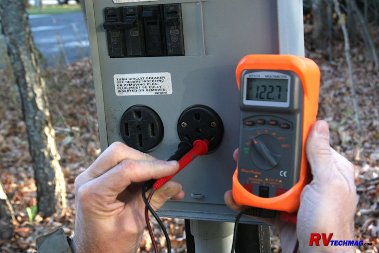
AC current operates differently. Batteries will always be DC and so were the first generators. A battery always has a
steady "push" of current. If you were to look at it on an oscilloscope you would be seeing a straight line extending across the screen
someplace above the center line. The actual height of this line will vary according to what the voltage is. A DC generator isn't the same
though. Because you have an armature rotating inside a housing with two field magnets you have a pulse every time the armature coil passes
a field coil and a dead spot when it's in between field coils. On an oscilloscope this looks very much like a bunch of waves on the top of
the ocean. DC current isn't all that efficient. That's why the automotive industry dropped DC generators in the early 1960s and went with
alternators. An alternator produces AC current and then uses diodes to rectify that into DC current. Let's look at a waveform comparison
of both AC and DC current to help understand the differences.
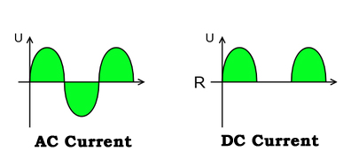
In the above illustration we have the AC waveform on the left and the DC waveform on the right. Voltage is plotted
vertically and identified as "U" on the graph so the higher the waveform, the greater the voltage. Time is plotted horizontally and
identified as "R" on the graph. We can see a large gap between the two "humps" on the DC graph. That's when the armature is in between
the field coils and the generator isn't producing any power. This is a characteristic of a DC generator. The graph on the left shows an
AC waveform. In this case positive polarity is above the center line while negative polarity is below the center line. You get twice the
power pulses, or "humps", in an alternator as in a DC generator. Adding built-in diodes to an alternator will rectify this current into DC
current so that it can feed the battery. The result is that an alternator is capable of higher outputs than a DC generator, especially at
low RPMs, such as during engine idle time. In the case of 120 volt high voltage systems the devices are all designed to run on AC power so
there is no need to rectify this current to DC. The only reason we still need to convert AC to DC in an automotive application is because
You cannot mix AC and DC current. Automotive applications rely on a battery to provide power to crank the engine, provide extra reserve
capacity when the alternator isn't quite enough, and to power accessories when the engine is not running.
We just mentioned the word "polarity" above. Polarity refers to whether or not a pole is positive or negative. Remember that
electrons flow from negative to positive so on a DC circuit they always flow in the same direction. A true AC circuit, such as a 120 volt AC
circuit, has polarity that constantly shifts, or alternates. That's why it's call "Alternating Current". Remember the earlier analogy of
the parade of electrons passing by and giving a series of "high fives" to the light bulb in the DC circuit? In an AC circuit the electrons
are constantly changing (alternating) direction. It's like they take one step, turn around and come back one step, then turn around and take
that same first step over again - and repeat this forever as if they really can't make up their mind. However, as long as an electron passes
by the light bulb, it will light up. With AC current it's the same electron, rather than a parade, but it's just dancing back and forth
underneath the same light bulb filament. Because the electron doesn't die after it's used this system works. All the other electrons just
act as a push-pull chorus line directing the movement of that electron. Therefore polarity really doesn't exist in an AC circuit, unlike
in a DC circuit, because it's constant changing. You still need to have a complete circuit, just as in a DC circuit, but there is no
positive or negative labeling involved. In a DC circuit the positive terminal is typically referred to as "hot" while the negative is
called "ground". In an AC circuit it's still advantageous to refer to the wires by names so these terms are replaced by "hot" and
"neutral" because there is no polarity and the higher voltages typically present require insulated return lines rather than a frame
grounding return.
That's about it for the basics of how electricity works. In the next section we'll talk more about volts, amps, and
watts and how they are all related.
Index
|